
Home / Case studies / Radar forward modelling
Tech-Log™ · Underground · radar modelling
Forward modelling
borehole radar reflectivity
Radargrams are hard to read when reflectors from several directions overlap. A forward-modelling workflow predicts what the radargram should look like from a simple geological scenario before drilling, then tests the interpretation against the field data, so boreholes can be placed well and genuine reef separated from clutter.
The question
Borehole radar (BHR) images reflective features close to boreholes and mine infrastructure: lithology contacts, fractures, faults, voids, dykes and orebody geometry. Its data are often complex to interpret, because features from multiple reflectors at different orientations around the hole are superimposed in one image.
Where a borehole is placed has a large effect on how complex the resulting radargram is. Placing it well can simplify the image considerably, but that needs a way to predict the radar response before drilling.
Forward modelling predicted the radargram from a simple geological scenario, matched the field data closely, and gave a defensible basis for placing boreholes and for telling genuine reflectors from overlapping clutter.
- SettingReef-hosted underground mining
- ToolBorehole radar, omnidirectional transmitter and receiver
- MethodForward modelling of reflectivity from simple geological scenarios
- CheckModel compared with the measured radargram
What we did
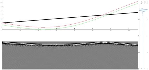
A modelling workflow predicts the shape of reflectors in a radargram from a simple geological scenario. In the example, a planned borehole starts within the reef, trends upward across a local depression, and is targeted to intersect the reef again towards the end of the hole.
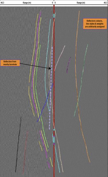
A simple model of that scenario includes both contacts of the thin reflective layer. The radargram derived from it shows both reflectors, and a V-shaped complexity between 100 m and 120 m where the borehole cuts through the reflective layer. Comparing the interpreted field section with the forward model showed excellent agreement for the main reflectors identified in the scenario, and with prior knowledge of the dominant structural orientations, the interpretation can be carried confidently into 3D.
What it changed
Borehole radar detected and imaged reef continuity, reef rolls and structures associated with brittle deformation. These results reduced uncertainty about reef geometry and continuity before development entered higher-risk areas, and supported safer, more continuous extraction by identifying where the reef was absent, displaced or significantly deflected.
Forward modelling gave a defensible basis for optimising borehole placement and for separating genuine geological reflectors from radargram complexity, which raised confidence in the 3D interpretation. Together these outcomes reduce avoidable development, limit exposure to unexpected ground conditions and focus follow-up drilling.
- Reef continuity, rolls and brittle structures imaged off-hole
- Zones of absent, displaced or deflected reef identified before development
- Borehole placement optimised on a predicted response
- Real reflectors separated from superposition effects
A transmitter and receiver moved along the hole send short electromagnetic pulses into the rock; contrasts in dielectric permittivity or conductivity reflect energy back. Because the antenna is omnidirectional, the radargram is a composite projection: planar contacts give continuous curved or dipping events, while points, edges and folds give hyperbolic, intersecting or V-shaped responses. Forward modelling converts the borehole trajectory and a simplified reflector geometry into the response to expect.