
Home / Case studies / Orienting radar reflectors
Tech-Log™ · Structure · 3D
Orienting radar reflectors
with televiewer images
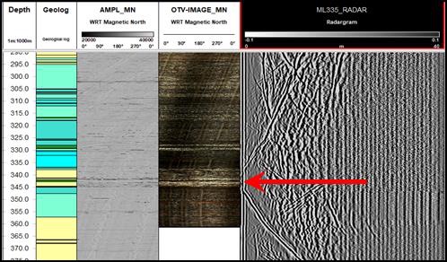
A radargram flattens omnidirectional reflections into a plane with no orientation. By matching each reflector to its intersection in oriented televiewer images, converting to true dip and dip azimuth, and rotating the radargram in 3D to those vectors, a dyke intersected at 342 m was digitised as a confidently oriented surface.
The question
The output of a downhole radar survey is a depth-based composite image in which omnidirectional reflection information is flattened into a single plane of unspecified orientation. Once all the reflectors are represented, this 2D image can be complex, and making sense of it takes experience.
The interpreter's challenge is assigning viable orientations to the reflectors. For the most part this has been done with a priori information such as known geological dip and dip azimuth, where reflectors correlate with geology. But what of cases where that prior data is unsuitable, or the reflectors do not correlate with known geology, such as faults or shears of unknown orientation? A robust workflow was required to separate individual reflection events, correlate them against other oriented data captured downhole, and assign high-confidence orientations.
Combining oriented televiewer images with the unoriented radargram in one 3D workflow assigned high-confidence orientations to near-hole reflectors out to the limit of radar penetration, producing a repeatable method for de-risking mine planning.
- ToolsAcoustic televiewer, optical televiewer and borehole radar in one hole
- TrajectoryGyroscopic deviation survey
- FeatureDyke intersection at 342 m to 343 m
- OutputDigitised, oriented dyke surface in 3D
What we did
A suite of downhole tools was run in the target borehole, including acoustic televiewer, optical televiewer and borehole radar. In most cases only one televiewer data set is available, depending on casing depth, water level and turbidity at the time of logging. Combining the oriented, ultra-high-resolution wall images with the unoriented, fine-resolution radar data in a single workflow makes it feasible to orient near-hole reflectors out to the limit of radar penetration.
The dyke intersection was identified in both the ATV/OTV images and the radargram between 342 m and 343 m. Upper and lower apparent dip and dip azimuth were determined from the oriented images and converted to true dip and dip azimuth for use as vector inputs to the 3D interpretation. Where more than one reflector is of interest, each is interpreted individually.
In the 3D environment the borehole trajectory was established from the gyroscopic deviation survey. The true dip and dip azimuth of the reflector were input as down-dip vectors, the radargram images were imported and attached to the borehole path, and rotated around the hole until aligned with the down-dip vectors. With the radargram correctly oriented, the reflector was defined by digitising points along its length, and a surface created from those points visualised the dyke in 3D.
What it changed
Integrated processing of borehole radar and oriented televiewer image data has significant potential to aid the interpretation of intersected radar reflectors. The methodology is robust and repeatable, resulting in high-confidence interpretations that de-risk and aid mine planning. The complete up-dip and down-dip dyke intersection was presented as a digitised surface.
- Reflector orientation from measured data, not assumed geology
- Faults and shears of unknown orientation become interpretable
- Radargram correctly rotated in 3D around the gyro-surveyed trajectory
- Repeatable workflow for every hole that carries both radar and imaging
Radar reflections occur at contrasts in dielectric permittivity, typically lithological contacts and brittle structures, and are recorded as a 2D radargram with no azimuthal information. Televiewer images carry an onboard orientation reference for every scan line, so a feature seen in both data sets lends the radargram its orientation. Down-dip vectors from the televiewer tadpoles are the key that aligns the two.