
Home / Case studies / Induced flowmeter logging
Hydro-Log™ · Hydrogeology · conductivity
Hydraulic conductivity
from flowmeter logging
Packer tests give a handful of hydraulic conductivity points per hole and can miss thin flow features entirely. Running an impeller flowmeter under constant induced pressure, sampled every centimetre and blocked to one-metre intervals, delivers hydraulic conductivity along the whole borehole and sites the packers where they matter.
The question
For the hydrogeologist, locating not just the currently active aquifers but every zone with flow potential is of prime importance to a reliable hydrological model. For the most part, hydraulic conductivity has been obtained by discrete point measurements such as packer testing. Cost, time and the physical size of the equipment limit the number and location of tests in any hole, and packer positions are usually chosen from core logs, so thin single-fracture flow points are easily overlooked.
The likelihood of missing flow points is therefore elevated, and downstream model reliability suffers from the non-continuous, low-resolution nature of packer results. Impeller flowmeters have been in the logging industry for years but are generally run under steady-state conditions: the data is temporal, varies day to day and season to season, and shows only the flow points active at the time of logging.
Induced-flow impeller logging mapped both broad flow zones and thin flow points continuously along the hole, producing measured hydraulic conductivity that sited packers better, filled the gaps between tests and, where needed, replaced packer testing altogether.
- MethodImpeller flowmeter logged under constant positive wellhead pressure
- Sampling1 cm continuous, block-averaged to 1 m intervals
- OutputsVertical flux (m³/min) and hydraulic conductivity (m/min) per interval
- CompanionsFluid temperature and conductivity, ATV or OTV imaging
What we did
Keeping the well under constant positive pressure while impeller flowmeter logging is conducted overcomes the shortfalls of non-induced steady-state measurements. Wider flow zones and thin flow points are accurately located on the borehole wall and the corresponding egress flow volumes measured, including both active and inactive flow points, thanks to the greater pressure differential.
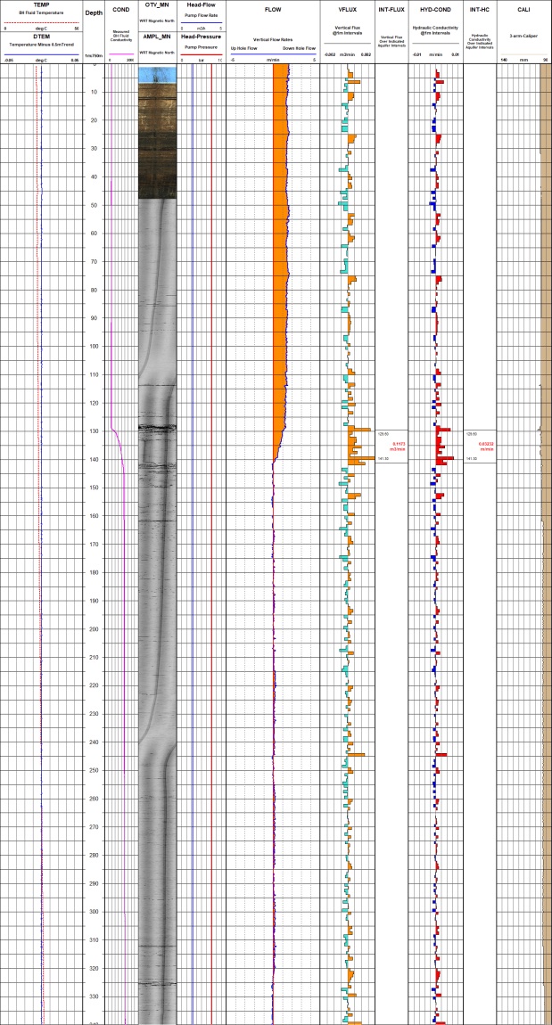
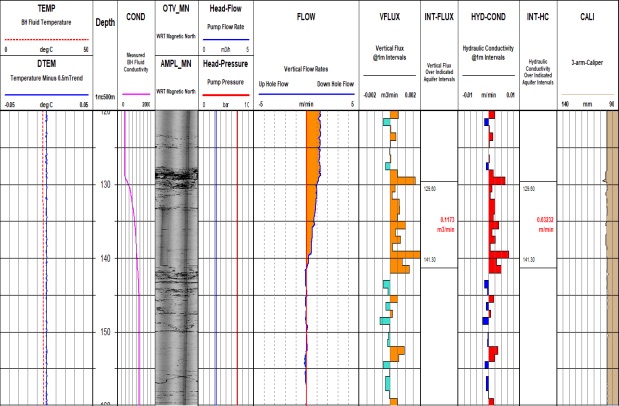
Acquired data includes wellhead flow and pressure monitoring along with the downhole impeller flow profile, all with 1 cm continuous vertical sampling. The impeller profile is corrected for pumping-induced artefacts using the wellhead pressure and flow information, then block-averaged to 1 m intervals. A modified form of Darcy's law is applied to calculate an estimate of vertical flux and hydraulic conductivity for each interval over the entire log length. Block averages over broader zones are calculated where required.
Incorporating fluid temperature and conductivity, and borehole wall imaging from acoustic or optical televiewers, gives greater insight into the location, magnitude and appearance of any aquifer or potential aquifer intersected down the length of the well.
What it changed
Clear and detailed mapping of flow zones, broad or thin, is now possible with regular sample spacing over the entire borehole, as the detail across an aquifer between 120 m and 160 m in the example plot shows. Estimating hydraulic conductivity this way facilitates better packer placement and acts as a separate correlation parameter, increasing data certainty in downstream hydrological models. Where steady-state flow logs produce too few results because natural flow is low, and where packer testing is unavailable or impractical, the method gathers hydraulic conductivity values that would otherwise not be attainable.
- Hydraulic conductivity for every metre of the hole, not a handful of packer intervals
- Thin single-fracture flow points captured, not overlooked
- Packer tests sited on evidence, supplemented or replaced
- Independent correlation parameter for the hydrological model
An impeller flowmeter records fluid velocity as it is trawled along the hole. Under induced flow the well is held at constant positive pressure at the wellhead, so every zone with flow potential contributes measurable egress. Wellhead pressure and flow are logged simultaneously and used to correct the downhole profile before Darcy's law converts blocked flow differences into vertical flux and hydraulic conductivity.