
Home / Case studies / Venetia pit slopes
Tech-Log™ · Diamonds · pit slopes
Kimberlite slope stability
at Venetia diamond mine
Pit slope stability at Venetia is controlled by the angle between the slopes and the rock's foliation, joints and faults. Televiewer images from vertical and inclined holes, including blast holes, built the structural database behind the 2008 to 2011 pit optimisation, faster and with far less drilling than oriented core alone.
The question
Venetia mine undertook a pit optimisation project between 2008 and 2011. The geotechnical model and slope designs were updated to take account of how the pit slopes are oriented relative to the foliation and jointing in the rock, and the project needed as much foliation, joint and fault orientation data as possible.
The country rock is mainly metamorphic and igneous rock of the Limpopo Mobile Belt. Pit stability is structurally controlled, by ductile structures (foliation) and brittle structures (joints and faults). A dominant metamorphic foliation cross-cuts all the geology, giving the rock mass an anisotropic strength, and the interaction between the brittle jointing and the ductile foliation locally affects bench stability and performance. Slope stability therefore depends heavily on the orientation of each pit slope relative to these structures.
Televiewers turned every hole in the area of interest, vertical or inclined, into a source of oriented structural data, building the foliation, joint and fault database for the pit slope optimisation faster and with significantly less drilling.
- SiteVenetia diamond mine, Limpopo Mobile Belt, South Africa
- ProgrammePit optimisation, 2008 to 2011
- ToolsAcoustic (ATV) and optical (OTV) televiewers
- DeliverableFoliation, joint and fault orientations for the geotechnical model
What we did
Oriented core drilling had long been the standard way to measure foliation and joint orientations at Venetia and elsewhere. It has one inconvenient limitation: core can only be oriented in inclined holes, not in subvertical ones.
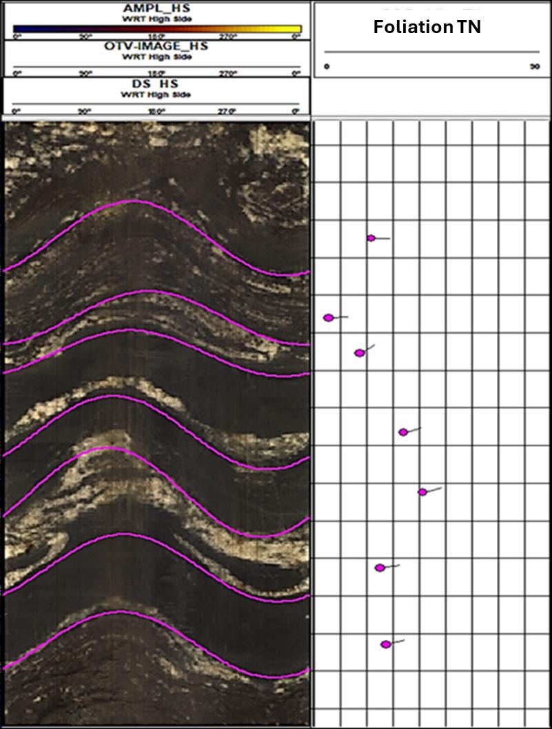
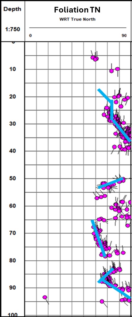
Televiewers capture oriented images of the borehole wall, a digital twin of the hole, in vertical and inclined holes alike and with no need for core orientation. Any hole logged within an area of interest becomes a source of structural information, blast holes included. In the optical image, foliation is clearly defined and easy to interpret, and plotting the picks down the hole reveals how the foliation orientation changes with depth.
What it changed
Using televiewers across the mine, alongside oriented core, made it possible to build a large database of foliation, joint and fault orientations. The data came in a shorter time than traditional methods alone would have allowed, and with significantly less drilling.
The data were instrumental in optimising the geotechnical domains and pit slope models (Ekkerd, 2011), resulting in faster, lower-cost and safer excavation design.
- Structural orientations from subvertical holes, where core cannot be oriented
- Blast holes turned into structural data sources
- Foliation trends tracked continuously down each hole
- Geotechnical domains and pit slope models optimised with less drilling
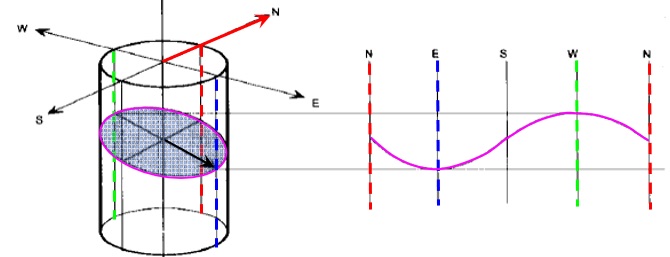
The acoustic televiewer images the wall with ultrasonic pulses, recording amplitude and travel time; the optical televiewer records a continuous, oriented, true-colour image and needs clear water or air. A planar feature crossing the hole appears as a sinusoid on the unwrapped image, and its amplitude and phase give the true dip and dip direction.